Operating Systems
Final Exam Review Questions
42 minute read
Notice a tyop typo? Please submit an issue or open a PR.
Final Exam Review Questions
P3L1
How does scheduling work? What are the basic steps and data structures involved in scheduling a thread on the CPU?
Scheduling is basically the responsibility that the OS has to run different task in the system on the CPU in a way that is fair an abides by certain semantics.
In order to achieve this, the scheduler must primarily maintain a runqueue, which is a data structure(s) that holds all of the tasks in the system in some meaningful way. The runqueue only has to be a queue logically; technically, it can be a multi queue structure or even a tree.
Scheduling can be done in a first-come-first-serve manner, in a round-robin manner, or in a more complex manner. If we know the amount of time a task will take, we can schedule the shortest jobs first.
The type of runqueue that we create depends on the scheduling policy that we want to enforce. For example, if we wish to have priority scheduling, it might make sense to maintain a runqueue for each priority level.
In order to schedule a task on the CPU, the scheduler must first remove it from the runqueue and actually schedule it on the CPU. Once it is running on the CPU, the scheduler needs to be able to preempt the task if a more important task comes along. In some cases, the scheduler may need to maintain a timer in order to evaluate when a timeslice expires. Once the scheduler preempts a task, it needs to place it back on the appropriate (potentially different) runqueue, and context switch to the next task in the system.
What are the overheads associated with scheduling? Do you understand the tradeoffs associated with the frequency of preemption and scheduling/what types of workloads benefit from frequent vs. infrequent intervention of the scheduler (short vs. long timeslices)?
The primary overhead with scheduling is one of timing. Specifically, the time to context switch between threads introduces some non-trivial amount of delay into the system. Context-switching frequently helps to reduce the wait time for any given task in the queue, but frequent intervention will drop the throughput and increase the average completion time.
Workloads that are primarily CPU-bound will benefit from longer timeslices, as they will be utilizing the CPU completely when they are scheduled. Workloads that are primarily I/O-bound will benefit from shorter timeslices, as frequent context-switching can help to hide latency.
Can you work through a scenario describing some workload mix (few threads, their compute and I/O phases) and for a given scheduling discipline compute various metrics like average time to completion, system throughput, wait time of the tasks…
For system throughput, take the total amount of time to finish all of the tasks, and divide by the number of tasks. For average time to completion, take the sum of the differences between the zeroth time and the time that each task completes, and divide by the number of tasks. For wait time, take the sum of the difference between the zeroth time and the time that each task starts, and divide by the number of tasks.
Don't forget that context switching takes time.
I/O bound threads that are waiting on requests cannot hide latency when there is no other thread to switch to, so don't forget to factor in request time in these cases.
Do you understand the motivation behind the multi-level feedback queue, why different queues have different timeslices, how do threads move between these queues… Can you contrast this with the O(1) scheduler? Do you understand what were the problems with the O(1) scheduler which led to the CFS?
The motivation behind the multi-level feedback queue was to have a single structure that maintained different timeslice levels that threads could be easily moved through. Queues have different timeslices because tasks have different needs. CPU-intensive tasks are better off have large timeslices because the shorter the timeslice, the more context-switching interferes with their task. I/O-intensive tasks are better off having a shorter timeslice. Since I/O-intensive operations issue blocking I/O requests, it's valuable to have them issue their request and then immediately be switched out, to hide the latency of their request. Maintaining a structure that has different queues for different timeslice values captures the complexity of the system. The scheduler can move threads through this structure based on preemption vs. yield observation. When a thread is consistently preempted, this is inline with the assumption that the thread is compute-bound. The scheduler can move this task to the end of a queue with a longer timeslice. When a thread consistently yields the CPU, this suggests that the thread is I/O bound. This thread should be moved to a queue with a smaller timeslice.
The O(1) scheduler maintains 40 different timesharing priority levels. The scheduler assigns the smallest timeslice to the compute-bound tasks, and the largest timeslice to the interactive tasks. The feedback for a task was based on how long it spent sleeping at its current priority level. Tasks that didn't sleep at all (CPU bound) had their priority decremented by 5, while tasks that slept more (I/O bound) had their priority increased by 5. In addition, each priority level maintained two queues, one active, one expired. The active queue contains the tasks that are actively being scheduled on the CPU. Each of these tasks must expire its entire timeslice before it is moved to the expired queue. Only after all tasks are expired do the active queue and the expired queue swap places.
The problem with this approach is that tasks had to wait until all of the other tasks, in all of active runqueues at all of the levels of higher priority, exhausted their timeslices. This introduced unacceptable jitter in applications that needed to be performant in realtime, such as Skype. As a result, the completely fair scheduler was introduced. This scheduler maintained a balanced tree structure, where each the left subtree contained tasks that had ran for less time on the CPU, and the right subtree contained tasks that had ran for longer time on the CPU. The scheduler always picks the leftmost task on the tree - the one that ran the least amount of vruntime. After some point of scheduling, the scheduler updates the vruntime of the task and either preempts it - if there is a new task with the lowest vruntime - or continues to execute it. For tasks with lower-priority, these updates happen more quickly while for tasks with higher-priority these updates happen more slowly.
Thinking about Fedorova's paper on scheduling for chip multi processors, what's the goal of the scheduler she's arguing for? What are some performance counters that can be useful in identifying the workload properties (compute vs. memory bound) and the ability of the scheduler to maximize the system throughput?
The goal of the scheduler that Fedorova is arguing for is a scheduler that maximizes CPU utilization in hardware multithreaded environments. Normally, we look at a metric called instructions per cycle (IPC) to determine utilization. Tasks that are CPU-bound typically have IPCs that are close to 1, while tasks that are memory-bound typically have IPCs that are closer to 0. Hardware counters can provide IPCs counts for the execution contexts that they manage. Federova is suggesting that hardware incorporates a new metric, cycles per instruction (CPI), which is the reciprocal of IPC. Compute-bound tasks would still have a CPI of close to 1, while memory-bound tasks would have a CPI much higher than 1. With synthetic workloads that consist of tasks with different combinations of CPIs, she showed that the IPC value for the most varied combination was the closest to 1. As a result, she concluded that - given her synthetic workload - CPI would be a helpful metric track and thus help improve platform utilization. Unfortunately, empirical values of CPI did not vary nearly as much as her synthetic workloads.
The IPC performance counter is helpful in determining if a task is compute-bound or memory-bound. In addition, performance counters that track cache misses can be helpful. With high cache misses, a scheduler can assume a task is making lots of memory access and therefore is memory-bound. With few cache misses, a scheduler can assume a process is more compute-bound.
P3L2
How does the OS map the memory allocated to a process to the underlying physical memory? What happens when a process tries to access a page not present in physical memory? What happens when a process tries to access a page that hasn't been allocated to it? What happens when a process tries to modify a page that's write protected/how does COW work?
The OS maps the memory allocated to a process to the underlying physical memory primarily via page tables. Page tables are kernel-maintained data structured that map virtual addresses to physical addresses. Each entry in a page table contains one such mapping. The mapped physical address is passed to the memory management unit (MMU) which performs the actual access.
If the page is not present in physical memory (i.e. it has been swapped out), the MMU will generate a fault. The OS will see that the present bit is set to 0, and will pull in the page from some secondary, disk-based storage.
If a process tries to access a page that hasn't been allocated to it, the MMU will again generate a fault. The OS will detect that this page hasn't been allocated and will perform some corrective action, potentially passing the fault along to the offending process as a SIGSEGV.
If a process tries to modify a page that's write protected, the MMU will generate a fault. Normally, this will result in some sort of punitive action, like program termination. However, this may happen frequently in the case when a child process has been forked from a parent process. In this case, since a lot of the address space of the parent contains static data that will be used by the child, it doesn't make sense to explicitly copy all of the data over to a new address space of the child process. Instead, the OS will often just point the child to the page tables for the parent. Additionally, the OS will write-protect the memory associated with the parent. If the child tries to write to a page, the MMU will trap into the kernel, at which point the OS will copy over the page(s) to the child address space. This process is called copy-on-write and makes sure that a child only copies over the pages it ends up writing.
How do we deal with the fact that processes address more memory than physically available? What's demand paging? How does page replacement work?
If we have a 32-bit architecture, with 4kB pages, each process can address 4GB of memory. If we have 8GB of RAM, 3 concurrent processes can (if they really wanted to) exhaust our RAM and then some. To deal with the situation where processes address more memory than is physically available, we have to introduced swapping/demand paging.
In demand paging, the operation system basically swaps out certain pages to secondary storage, like disk. This changes the present bit to 0 on the addresses associated with that page, which means that the MMU will trap into the kernel on access to those pages, at which point the OS will have to bring those pages back into DRAM. Note that the physical addresses will NOT be the same when the OS brings a page back from storage. That's the point of maintaining virtual addresses. When a page is brought back in, the program counter is reset back to the instruction that made the original trapping reference, and the successful reference is now made.
To swap pages out, we have to run a page swapping daemon. This daemon can look at the pages that are least-recently used and swap those pages out. The rationale behind this strategy is that pages that have been used recently are likely to be used in the near future. This is the LRU approach. We can look at the access bit to determined whether or not a page has been accessed. In addition, we can swap out pages that don't need to be written to disk, since writes take time. We can look at the dirty bit, which tracks writes, to surface this information.
Linux by default uses a modification of the LRU cache that incorporates a second chance. This modification performs two scans before swapping to disk.
How does address translation work? What's the role of the TLB?
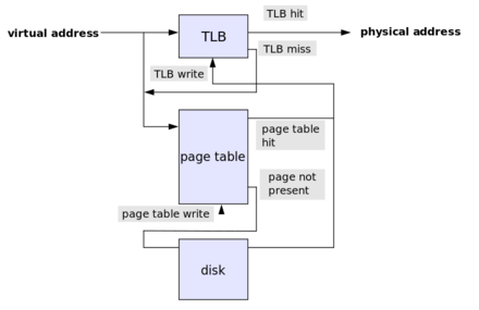
Virtual address first passed to the translation lookaside buffer (TLB), which is a hardware-maintained cache of address translations. If this cache has a present physical address for the virtual address, the access can proceed. Otherwise, the OS has to walk the page table, and find the appropriate translation for the virtual address. Once this mapping is found, it is written to the TLB and access proceeds through the TLB.
In the simplest case a virtual address consists of just a virtual page number (VPN) and an offset. The VPN is used to index into the page table and produce a physical frame number (PFN). This PFN is combined with the offset to produce the exact physical address.
Note that we have to provide two memory accesses to access our memory. One access is performed to look up the PFN from the VPN, and the other looks up the actual physical address. With hierarchical tables, the number of access required for a physical memory address grows with the number of layers. Here, the TLB can really speed up the translation: there is always only one TLB lookup for a given memory address.
While the OS maintains the page table, accesses must proceed through the TLB.
Do you understand the relationships between the size of an address, the size of the address space, the size of a page, the size of the page table…
For an address size of X bits, a process can address 2^X memory locations. For a page-size of 2^Y bits, a page table will have 2^(X-Y) entries. Since each entry in a page table is X bits, a page table will occupy 2^(X-Y) * X bits.
In a 32-bit architecture, where addresses are 32 bits long, each page table can address up to 2^32 (4GB) of data. Since a physical memory page is often 4KB in size, this page table would have 2^20 entries. Since each entry is again 4 bytes (32 bits), the entire page table is 4MB in size.
Do you understand the benefits of hierarchical page tables? For a given address format, can you workout the sizes of the page table structures in different layers?
Hierarchical page tables allow us to map virtual addresses to physical addresses without maintaining an entry for every virtual address. With a two level page tables, we have a page table directory whose entries are page tables. Each page table ends up addressing a smaller region of physical memory. When a process needs to allocate some memory, the OS may address from an existing page table or it may generate a new page table. This way, the amount of mapping that the OS maintains more accurately reflects the amount of memory the process is actually using.
Let's look at an example with 32 bit addresses that are broken into a 12 bit segment, a 10 bit segment, and a 10 bit segment. The first segment indexes into the page table directory. This means that the OS can maintain 2^12 page tables in the directory. Each page table maintains 2^10 entries, with each entry able to address 2^10 bytes. This means that each page table can address 1MB.
P3L3
For processes to share memory, what does the OS need to do? Do they use the same virtual addresses to access the same memory?
For processes to share memory, the operating system needs to map some segment of physical memory into the virtual address spaces of the processes. There is no guarantee (and it is likely impossible) that processes will use the same virtual addresses to access the same memory. It's the page tables that are important here. The OS needs to set up page tables such that some subset of virtual addresses for some group of processes point to the same block of physical memory. The virtual addresses can be "arbitrary": it's the mapping that matters.
For processes to communicate using a shared memory-based communication channel, do they still have to copy data from one location to another? What are the costs associated with copying vs. (re-/m)mapping? What are the tradeoffs between message-based vs. shared-memory-based communication?
When processes communicate with one another via a memory-based communication channel, data copying may be reduced but it is often not eliminated. For data to be available to both processes, a process must move the data to a portion of the address space that points to underlying shared physical memory. Data needs to be explicitly allocated from the virtual addresses the belong to the shared memory region. Otherwise, the data is local to the process.
In message-based IPC, the benefit is the simplicity. The developer doesn't have to manage any synchronization or any actual data management or channel setup. The OS handles everything. However, this comes at a cost. We have to context switch to and from the kernel to pass a message from one process to another, and this involves copying data twice: into and out of the kernel. This is relatively expensive.
In shared-memory IPC, the benefit is the relatively low cost. While the shared memory mapping that the OS creates is relatively expensive, that cost is amortized over the lifetime of that memory channel. However, since the OS is completely out of the way, it's up to the developer to manage everything. Synchronization, channel management and data movement are no longer free.
The cost associated with copying data - in the case of message-based IPC - is two-fold. The data has to be copied, into and out of the kernel's address space - since the kernel manages the channel - and during this process, we have to context switch to the kernel from the user process and back again. This means that a request-response cycle will take four context switches and four data copies. The cost associated with mapping memory is still large, but it's a one-time cost. It may even be amortized across one request-response cycle if the data is large enough.
What are different ways you can implement synchronization between different processes (think what kind of options you had in Project 3).
Synchronization can be implemented across different processes with mutexes. Just like we can control access to shared resources across threads with mutexes and condition variables, we can control access to shared resources across processes with the same synchronization constructs. We have to set a few additional flags to make sure that these constructs work across processes.
Additionally, semaphores (binary mutexes) can be used to implement synchronization across processes. When one process access shared memory it decrements the semaphore to zero. Other processes will then be blocked on the semaphore. When the process is done accessing shared state, it can increment the semaphore, allowing another process to secure it.
Finally, message-based IPC can be used to help kick off a shared memory access session. For example, a client process can send a message - via message queues - to a server to request some response be placed into shared memory. The client can then sit on a semaphore associated with that shared memory, which the server can unlock after it writes its response.
P3L4
To implement a synchronization mechanism, at the lowest level you need to rely on a hardware atomic instruction. Why? What are some examples?
Basically, we need atomic operations because the checking of a lock and the setting of a lock require multiple CPU cycles. We need these cycles to be performed together or not at all: atomically. Some examples of atomics include: test_and_set, read_and_increment, and compare_and_swap.
Why are spinlocks useful? Would you use a spinlock in every place where you're currently using a mutex?
On one hand, spinlocks are very simple to implement. There is use in simplicity. In addition, they are pretty simple to understand. You just burn through CPU cycles continuously checking the value of the lock until you are preempted. As well, spinlocks have very low latency and very low delay. You probably wouldn't want to use spin locks every place you are currently using a mutex, however. What's nice about mutexes is that, after checking a lock that isn't free, the process will immediately relinquish the CPU. This can have some performance considerations. That being said, when a spin lock is relinquished there is pretty much no delay in that link being acquired by the next in line.
Do you understand why is it useful to have more powerful synchronization constructs, like reader-writer locks or monitors? What about them makes them more powerful than using spinlocks, or mutexes and condition variables?
These constructs are more powerful because of their expressiveness. Using a reader-writer lock instead of a two binary semaphores to control the access of shared state allows you to express implement the semantics of your application with higher-level code. This means that there is less room for error. We saw that mutexes were limited in their expressiveness. We had to introduce proxy variables to mimic the control we wanted to have. In addition, we save that it was easy to make mistakes with mutexes. Locking the wrong mutex and signaling on the wrong condition variable are not hard mistakes to make. Dealing with higher-level semantics that abstract away some of the lower-level components helps developers reduce the area for mistakes.
Can you work through the evolution of the spinlock implementations described in the Anderson paper, from basic test-and-set to the queuing lock? Do you understand what issue with an earlier implementation is addressed with a subsequent spinlock implementation?
Test-and-Set
This lock has super low latency. Since it spins directly on the atomic, it will know immediately when the lock has been freed. This lock has a super low delay as well. As soon as a lock is freed, the very next instruction that this process will execute will be the atomic. From a contention perspective this lock is pretty bad. We constantly have to go to memory on every spin, which can increase traffic on the shared interconnect.
Test-and-test-and-set
This lock no longer spins on the atomic, which is good. Instead, it spins on the cached value of the lock. This means that the lock is a little bit worse in terms of latency, and delay. From a contention standpoint, the performance varies. With a write-update strategy the performance improves, as the hardware will update the value of the cache to reflect the new locked value. With a write-invalidate strategy, the performance is awful. Every single attempt to acquire the lock will generate coherence traffic.
Delay lock
One problem with the contention is that all of the lock contenders see the attempt the atomic at the same time. After the delay expires, the thread can attempt to acquire the lock if the cached value if it sees that the lock is still free. From a latency perspective, this lock is okay. We still have to perform a reference to bring the lock into the cache and another to perform the atomic. This lock is much better from a contention perspective, but is much worse from a delay perspective since we have introduced this artificial delay.
Queueing lock
The queueing lock uses an array of flags with up to n elements, where n is the number of threads in the system. Each element in the array will have one of two values: either has_lock or must_wait. In addition, one pointer will indicate the current lock holder (which will have a value of has_lock), and another pointer will reference the last element on the queue. When a new thread arrives at the lock, it will receive a ticket, which corresponds to the current position of the thread in the lock. This will be done by adding it after the existing last element in the queue. Since multiple threads may enter the lock at the same time, it's important to increment the queuelast pointer atomically. This requires some support for a read_and_incremement atomic. For each thread arriving at the lock, the assigned element of the flags array at the ticket index acts like a private lock. As long as this value is must_wait, the thread will have to spin. When the value of the element is becomes has_lock, this will signify to the threads that the lock is free and they can attempt to enter their critical section. When a thread completes a critical section and needs to release the lock, it needs to signal the next thread. Thus queue[ticket + 1] = has_lock. This lock is better from a contention standpoint and delay standpoint, but it does rely on the read_and_increment atomic and takes more space than other locks.
P3L5
What are the steps in sending a command to a device (say packet, or file block)? What are the steps in receiving something from a device? What are the basic differences in using programmed I/O vs. DMA support?
When an application needs to access a device, it will make a system call specifying the appropriate operation. The kernel will execute some formatting steps on the request before passing them down to the device drivers. The device drivers will interact with the device itself via PIO or DMA. Alternatively, in OS bypass, a user-level linked library can be utilized by the application to write directly to the device registers.
For the information to travel back to the CPU, it can take two routes. The device can generate an interrupt to trap into the kernel. This allows the CPU to see information about a request as soon as it is available, but incurs some interrupt handling overheads. Alternatively, the CPU can poll some status registers associated with a device
In PIO, the CPU writes all of the necessary information directly into the registers associated with a device. This will include the command and the data registers. Something to consider about this approach: registers are relatively small, so to send large amounts of data to a device in this approach requires the CPU to write data and receive an acknowledgement over and over again. One nice part of this is that this method requires no additional hardware support. Alternatively, with direct memory access, the device can access DRAM directly. The CPU can establish a buffer in DRAM and the device will be able to read it without having to rely on the CPU as an intermediary. However, this requires additional hardware in the form of DMA controller.
For block storage devices, do you understand the basic virtual file system stack, the purpose of the different entities? Do you understand the relationship between the various data structures (block sizes, addressing scheme, etc.) and the total size of the files or the file system that can be supported on a system?
At the top there is the file API that user applications interact with. Below the file interface is the filesystem. The filesystem will actually interact with the block devices via their device drivers. Different devices will have different drivers, which can have different APIs. As a result, the final level above the device drivers is the generic block layer, which provides a standard API to the filesystems for interacting with storage devices. In a virtual filesystem, there is a VFS layer on top of the actual filesystems that gives the appearance of a single cohesive filesystem.
The file is the main abstraction on which the VFS operates. The file is represented to the higher level applications by an integral file descriptor. Each file is maintained by the VFS through an inode structure, which holds an index of all of the blocks for a given file. To help with operations on directories, the OS will maintain a structure called a dentry which corresponds to a single path component that is being traversed. Finally, there is a superblock that maintains overall information about how a filesystem is laid out on disk.
The size of the inode can directly determine the size of the file. For example, if we have a 128B inode containing 4B pointers addressing 1kB blocks, we can only have files that are 32kB in size. To get around this, we can use indirect pointers. For example, we can point to a block of pointers. A 1kB block of 4B pointers points to 256 blocks of 1kb of memory lets us address 256kB of memory.
For the virtual file system stack, we mention several optimizations that can reduce the overheads associated with accessing the physical device. Do you understand how each of these optimizations changes how or how much we need to access the device?
Filesystems can use caching to place blocks in main memory and reduce the the number of disk accesses. Filesystems can also utilize I/O scheduling. One of the largest overheads is actually moving the disk head, so the I/O scheduler can reassemble requests such that the disk head has to backtrack as infrequently as possible. In addition, we can utilize prefetching. Instead of just fetching a block that is requested, it may be optimal to fetch that block and the next three logical blocks (the inode can help us understand what those blocks are). In addition, we can use journalling. Instead of immediately writing every request to disk, we can instead apply them to a log. These writes can then periodically be applied to the proper disk locations.
P3L6
What is virtualization? What's the history behind it? What's hosted vs. bare-metal virtualization? What's paravirtualization, why is it useful?
Virtualization is the process by which multiple operating systems can be run atop of a single hardware platform such that each operating system thinks that it has direct, complete access to the hardware platform below it. In reality, a virtualization machine monitor (VMM) is responsible for coordinating and arbitrating the underlying hardware accesses.
In bare-metal virtualization, the VMM runs directly atop the hardware platform. In hosted virtualization, the VMM runs as kernel software within an operating system on the host. Bare-metal virtualization suffers from issues with device access - primarily the non-uniformity of device interfaces. This issue is not suffered by host virtualization, which can leverage a lot of the machinery already present in the host kernel for accessing devices via drivers that are already present.
Paravirtualization is a model whereby the guest operating system knows that it is running a virtualized environment. This allows for some optimizations with regard to x86 problems (see 2) and device access (see 3).
What were the problems with virtualizing x86? How does protection of x86 used to work and how does it work now? How were/are the virtualization problems on x86 fixed?
The main problem with virtualizing x86 platforms was that there were 17 hardware instructions that were privileged but did not generate a trap. This meant that the VMM was unable to detect - and thus grant - these instructions to be issued, since no trap occurred. In addition, it was a silent failure for the guest OS, since the instructions would not be executed, but no error was raised.
Back in the day, x86 platforms only had one protection mode - root. This mode had four rings, with 0 having the most permissions and 3 having the fewest. A VMM would run in ring 0, a guest OS would run in ring 1, and a guest user application would run in ring 3. Now, x86 platforms have two protection modes - root and non-root. VMMs run in root 0, and guest OSes run in non-root 0.
The virtualization problems on x86 were eventually fixed by the chip makers, which ensured that the 17 privileged hardware instructions did generate a trap. In the meantime, there were two additional solutions.
On the one hand, there was binary translation. In this model, the VMM would capture blocks of code issued from the guest OS. If a block contained one of the 17 instructions, the VMM would rewrite the code block to not contain the instruction, while still emulating the desired behavior. This solution added latency overheads, but allowed guest OSes to not be modified.
One the other hand, there was paravirtualization. In this model, the guest OS knows that it is running in a virtualized environment. A paravirtualized guest will perform operations that it knows will fail, but will rather make explicit calls known as a hypercalls. These hypercalls will trap into the VMM, which can then emulate the desired behavior. While this reduced some of the overheads of binary translation (full virtualization), this required guest OSes to be modified.
How does device virtualization work? What a passthrough vs. a split-device model?
Device virtualization is challenging. There is standardization around CPUs and memory units at the level of instruction set architecture. This means that for a given ISA, the number of operations that a virtualization layer will need to support will be very standardized. This is not the case with devices; with regard to device interfaces, there is much greater diversity in the landscape. Different models have been adopted to adopted to allow for device virtualization.
In the passthrough model, the VMM layer establishes access to a specific device to a VM that is requesting that device. Once the access is established, the VMM is out of the way. This means that the guest OS must have the exact drivers necessary to communicate directly with that device. The main problem with this solution is that it breaks the decoupling of the operating system and the hardware, a problem that virtualization largely solves. Now the guest OS must know something about the underlying platform, which makes things like migration more difficult. Another difficulty of this method is that device sharing become really difficult, as the VMM layer must constantly reassign the device registers to a new VM
In the hypervisor direct model, the VMM layer intercepts every request for device access and translates it into a more generic I/O device type request that be transformed and ultimately passed to the native device driver and underlying platform. This model has strength in the fact that it decouples the guest from the platform. However, the interception of every request by the VMM introduces device access latency that is often unacceptable.
In the split-device driver model, there are two sets of device drivers: one that sits in the guest VM, and one that sits in the host OS - in the case of type 2 virtualization - or the service VM - in the case of type 1 virtualization. In this model, the back-end driver issues the actual requests down to the hardware. The front-end driver must wrap the requests that it wants to make in a standardized format that the back-end driver can interpret. As a result, the guest OSes will need to be modified to make these customized requests, which means that the split-device driver model really only works in paravirtualized environments - where the guest knows that it is running in a virtualized environment.
P4L1
What's the motivation for RPC? What are the various design points that have to be sorted out in implementing an RPC runtime (e.g., binding process, failure semantics, interface specification… )? What are some of the options and associated tradeoffs?
RPC was motivated by the observation that client/server programs contained a lot of the same communication/transport-level boilerplate code. RPC sought to autogenerate some of that code in order to allow developers to focus on developing the interesting parts of their applications.
There are a few different design options. With regard to binding, clients can interact with a global registry, a machine-based registry, or anything in between. A global registry will have a lot of traffic to maintain, while a machine-based registry will require that the client knows which machine the server is on. With regard to failure semantics, it can be difficult for the RPC runtime to adequately deliver meaningful failure messages since so many things can go wrong that are outside of the control of the RPC program. Interface specifications can be language-specific or language-agnostic. Language-specific IDLs are great if you know the language and don't want to learn yet another "language". Language-agnostic IDLs are great if you don't want to learn another programming language just to be able to use RPC.
What's specifically done in Sun RPC for these design points – you should easily understand this from your project?
RPC uses a machine-based registry approach: a client must know the machine the server is running on in order to connect. With regard to failure semantics, SunRPC exposes a number of error codes that can be returned from an RPC call. With regard to the IDL, XDR is a language agnostic IDL.
What's marshaling/unmarshalling? How does an RPC runtime serialize and deserialize complex variable size data structures? What's specifically done in Sun RPC/XDR?
Marshaling refers to the process of taking data from disparate locations and putting them into a single buffer, likely to be sent across the network. Unmarshalling refers to the processes of removing chunks of data from a contiguous buffer into disparate variables. This is necessary because communication mechanisms like sockets require data to be sent in a contiguous buffer.
An RPC system will have to specially encode variable length arrays. In SunRPC, variable lengths arrays are represented in code as structs with two fields. The first field will contain an integer representing the length of the data. The second field will be a pointer to the data. In addition, strings will be encoded with length and data fields, although they will be represented in memory as plain null-terminated strings.
P4L2
What are some of the design options in implementing a distributed service? What are the tradeoffs associated with a stateless vs. stateful design? What are the tradeoffs (benefits and costs) associated with using techniques such as caching, replication, partitioning, in the implementation of a distributed service (think distributed file service).
There are many different design options when implementing a distributed service.
On one hand, everything can be driven through the client. This is nice because it makes the server super simple. Unfortunately, the client now has to download and re-upload all files, even for very small modifications. In addition, the server completely loses control over files. On the other, hand everything can be driven through the server. This is nice because the server retains control over the files. Unfortunately, every file operation must incur a network cost, which limits the scalability of the server.
Replication can be a powerful technique. Replication involves duplicating files across all nodes in the system. This is helpful because any node can service any file request. If a node goes down, any other node can be used. This makes replicated systems highly available and fault tolerant. Unfortunately, these systems are harder to scale, since every node needs to hold all of the data.
Alternatively, partitioning can be another powerful option. Partitioning involves splitting the filesystem across nodes, such that each node holds some subset of the data. This system is a little bit trickier to reason about, since requests have to routed to the correct node, and node failures mean unaccessible content. However, these systems are super scalable. If you add another node, you can spread the filesystem thinner, reducing the load proportionately on all the other nodes in the system.
Caching can be a great technique that clients can leverage. Caching file content allows clients to not have to go to the server for every operation. This can improve performance for repeated reads, for instance. The first fetch can be cached, and further read from local cache. The downside of this approach is that coherence mechanisms must now be introduced into the server. If one client is reading from cache, and another client writes data corresponding to the chunk that the first client is caching, we need some way to allow that client to fetch the updates.
We can choose to have a stateful server or a stateless server. Stateless servers are easy; they just serve file content. That being said, stateless servers can't drive coherence mechanisms, so clients can't cache against stateless servers. Stateful servers are more complex, but also allow for more performant, expressive behavior.
Finally, we can choose what type of semantics we want to have when it comes to updates. In session semantics, updates to a file are pushed to the server when a file is closed. When a file is opened, the cache is skipped and the file content is pulled from the server. Alternatively, we can have periodic updates. In this case, the client will either write back data to the server periodically, or the server will send cache invalidation messages to the client periodically.
The Sprite caching paper motivates its design based on empirical data about how users access and share files. Do you understand how the empirical data translated in specific design decisions? Do you understand what type of data structures were needed at the servers' and at the clients' side to support the operation of the Sprite system (i.e., what kind of information did they need to keep track of, what kind of fields did they need to include for their per-file/per-client/per-server data structures).
The empirical data was as follows. The authors noticed that 33% of file access were writes, and 66% were reads. 75% of files were open less than 0.5 seconds, and 90% of files were open less 10 seconds. 20-30% of data was deleted within 30 seconds, and 50% of data was deleted within five minutes. They also noticed that concurrent writes (file sharing) was relatively rare.
As a result, the authors decided to support caching, and leverage a write-back policy. Every 30 seconds, the client would write-back the blocks that it hasn't modified in the past 30 seconds. Every write operation must go to the server. Every close operation does not write-back to the server: session semantics are not observed. This is because files are open for such short amounts of time that session semantics will still incur overheads that are too high. In the case of concurrent file access (file-sharing), caching is disabled. All operations are serialized server side. Since this doesn't happen often, the cost isn't significant.
On a per file basis, the client keeps track of:
- cache (overall yes/no)
- cached blocks
- timer for each dirty block
- version number
On a per file basis, the server keeps track of:
- readers
- writer
- version
P4L3
When sharing state, what are the tradeoffs associated with the sharing granularity?
Sharing at the granularity of the cache line is too fine-grained. The amount of coherence traffic that will be generated as a result of this strategy will outweigh any of the consistency benefits that will be gained.
Sharing the granularity of the variable may make more sense from a programmer point of view. This level of granularity may make it possible for programmers to specify sharing semantics on a per-variable basis. However, this level of sharing is still too fine-grained, and the level of network overhead will still be too high.
Sharing at the level of the page is a higher level of granularity, and one that makes sense to the OS. In this case, we must beware of false sharing, which can occur when two processes are concurrently accessing different portions of the same page. In this case, the coherence traffic that gets generated is unnecessary.
Sharing at the level of the object is also possible, but requires a language runtime to make this possible. The OS knows nothing about objects, so it needs no modification, which is a positive. However, requiring a specific language runtime for DSM makes object granularity a much less generalizable solution than something like page granularity.
For distributed state management systems (think distributed shared memory) what are the basic mechanisms needed to maintain consistence – e.g., do you why is it useful to use 'home nodes', why do we differentiate between a global index structure to find the home nodes and local index structures used by the home nodes to track information about the portion of the state they are responsible for.
We need to maintain consistency in two ways.
First, we need to make sure that when a node requests data it gets a relatively recent copy of that data. In order to do that, every node must maintain a map that connects an address/page to a specific home/manager node in the system. The requesting node will contact the home node in order to request the data that that node manages. The requesting node is then free to cache that data until a coherence request is sent out.
Secondly, we need to make sure that we broadcast when state has changed. Since each node manages a portion of the state, the home node for a piece of data will be responsible for driving the coherence mechanisms when a piece of state it owns changes. Since it needs to contact all of the nodes that have cached that page, it must maintain a per-page index of all of the nodes that have requested that page in the past.
In summary the global index structure helps nodes to always find the home node for an address/page, which can ensure that a node can immediately get the most recent value for an object. The local index structures maintained by a home node are necessary to drive coherence mechanisms that are directed only at affected nodes.
Do you have some ideas how would you go about implementing a distributed shared memory system?
One of the most important aspects of implementing a distributed shared memory system is intervening on memory accesses. We want the OS to be involved when we try to access memory that comprises part of the shared memory system, but we don't want the OS involved when accessing memory that is local to the node. Thankfully, we can leverage the memory management unit (MMU). On invalid memory references - which will arise when we try to access remote address locally - will generate a fault, which will cause the MMU to trap into the OS. At this point, the OS will to detect that the memory address is remote, and will leverage the address->home/owner node map to look up the home node that contains the address being requested. The OS will message that node via a message queue or a socket or some other IPC based communication mechanism, and request the data at the address. When the data is received, the OS can cache it on the CPU and return it to the process that requested it. Additionally, we need the OS involved when a process tries to write a piece of shared data. In this case, we need to write-protect virtual addresses that correspond to shared state. Writing to these addresses will cause a fault, which will trap into the kernel. The kernel will see that the access points to shared data at which point it will either send a message to the home node for that state in order to update it or, if it's the home node, update the data and broadcast coherence messages to nodes that are holding that data. It can determine which nodes hold the changing data by maintaining per page data structures that contain a list of nodes that have accessed that page. This means that when a node requests a page or an address, it should send its node ID as part of the request.
What's a consistency model? What are the different guarantees that change in the different models we mentioned – strict, sequential, causal, weak… Can you work through a hypothetical execution example and determine whether the behavior is consistent with respect to a particular consistency model?
Consistency models guarantee that state changes will be made visible to upper-level applications if those applications follow certain behaviors. A consistency model is model that a DSM layer abides by for makes memory updates available to the rest of the platform.
In a strict consistency model, all updates are made available everywhere, immediately. Immediately after an update to shared memory is made, any node in this system will be able to see this update. This strategy is not possible in practice. SMPs do not even offer this guarantee on single nodes.
In a sequential consistency model, updates are not required to be immediately visible. Instead, updates from different nodes can be arbitrarily interleaved. The only constraint is that the interleaving must be possible given the actual ordering of the updates in the system. For example, if node 1 writes A to memory location 1, and then node 2 writes B to memory location 2, it is legal for node 3 to see A at 1 and then B at 2. It is also legal for node 3 to see 0 at 1 and B at 2, or 0 at 1 and 0 at 2. However, it is not legal for node 3 to see B at 2 and then 0 at 1. In addition, updates from the same node cannot be arbitrarily interleaved. For example, if process 1 writes A at memory location 1 and then writes B at memory location 2, it will not be legal to see B at 2 before seeing A at 1. Finally, sequential consistency guarantees that two nodes access the same memory concurrently will see the same value.
In causal consistency model, the DSM layer tries to understand updates that may be causally related and enforce the ordering of such updates. For example, if node 1 writes X at memory location 1, and node 2 reads X and then writes Y at memory location 2, a causally consistent system will enforce that process 3 must read X at memory location 1 before reading Y at memory location 2. Since the writing of Y may have depended on the presence of X, the system will enforce that other nodes will see the right value at 1 if they are to see the new value at 2. Finally, causal consistency makes the same guarantee as sequential consistency: updates from the same node cannot be arbitrarily interleaved.
In the weak consistency model, the synchronization effort is placed back on the programmer. In this case, the DSM layer will export another operation, a synchronization operation. A node that is updating shared memory will invoke this synchronization operation, sometimes known as an exit/release operation, to make its updates available to the other nodes in the system. A node that is accessing shared memory will invoke an identical (or similar) operation, sometimes known as an entry/acquire operation, to bring updates from other nodes into its awareness.
P4L4
When managing large-scale distributed systems and services, what are the pros and cons with adopting a homogeneous vs. a heterogeneous design?
In a homogenous design, all of the nodes in the system are able to fulfill any request that enters the system. The benefit of this design is that the frontend load-balancing component can be simple. It simply needs to send requests to each of the nodes in a round-robin manner. Unfortunately, this design doesn't allow for any benefit from caching. The frontend component doesn't keep enough state in this design to understand the locality of tasks on a node-by-node basis.
In a heterogenous design, each node is specialized to fulfill some subset of requests that enter the system. The benefit of this design is that caching can be leveraged more effectively. With similar computations being performed on similar data, the possibility of actionable data being present in the cache increases. Our system has more locality. The frontend becomes more complex, as it now needs to know more about the system in order to route requests. A big downside is that the scaling opportunities become more complex. It's not longer enough to add or remove nodes in response to fluctuating traffic. In heterogenous systems, you'll need to understand which components of the system need to be scaled up or scaled down.
Do you understand the history and motivation behind cloud computing, and basic models of cloud offerings? Do you understand some of the enabling technologies that make cloud offerings broadly useful?
The history of cloud computing, from the perspective of Amazon Web Services, began in 2006. Amazon realized that the bulk of its hardware was being utilized only during the relatively short holiday season. For the rest of the year, a lot of their resources were underutilized. Amazon found that it could utilize that computing power in the offseason by renting out that power to third party workloads.
A more abstract motivation behind cloud computing has to do with the access to compute resources as a public good, similar to access to telephone services. In order to realize computing as a globally accessible public good, stable cloud computing models had to come to fruition.
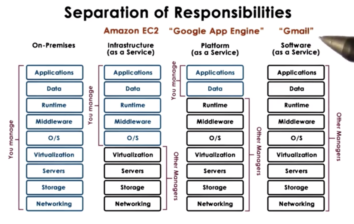
There are a few different models of cloud offerings. The offerings differ primarily along the axis of ownership, with cloud providers owning different portions of an application stack for different models.
In software as a service (SaaS) platforms, the provider owns the application, the data, the infrastructure, and the physical hardware. Gmail is an example of a SaaS platform.
In platform as a service (PaaS) systems, the provider owns the infrastructure and the physical hardware. The developer is responsible for bringing the application and that data. For example, the Google App Engine is a platform for developing android apps. The platform provides an environment for executing these applications, but the developer must bring their own application.
In infrastructure as a service (IaaS) systems, the providers owns the physical hardware. The developer brings the applications, the data, and is responsible for configuring the infrastructure, such as the middleware and the operating system. Amazon EC2 is an example of an IaaS platform.
There are many different technologies that enable cloud computing. Virtualization technologies help to make physical hardware into fungible resources that can be repurposed for different workloads. Technologies for resource provisioning help to ensure that resources are created quickly and consistently. Big data technologies - both for processing and storage - allow clients to scale very widely. Monitoring technologies are also crucial for enabling cloud computing. These technologies help datacenter operators preside over their data centers, responding quickly and effectively in the event of an incident. In addition, these technologies help clients perform similar sort of investigative tasks with respect to the applications they run in the datacenter.
Do you understand what about the cloud scales make it practical? Do you understand what about the cloud scales make failures unavoidable?
From the perspective of the cloud services provider, cloud computing is practical for two reasons. The first reason has to do with the law of large numbers. This states that with a large number of computing clients, the amount of resources that will need to be available will tend to be constant. As a result, the provider can purchase some fixed amount of hardware without worrying about fluctuations in individual client's peak consuming all of the resources. Secondly, cloud services are viable due to economies of scale. The fixed cost of hardware can be amortized across multiple clients sharing that hardware. Naturally, the best scenario is having many, many clients.
From the perspective of the cloud services client, cloud computing is practically because of the elasticity of resources and the corresponding elasticity of cost. Consider the case of Animoto, which had to scale up its resources by a factor a two orders of magnitude over the period of a week. With a traditional, on-premises setup, this type of scale would not have been possible. Data centers allow for seamless scaling. As a result, the cost incurred by computational consumption can better mirror potential revenue influx. If we assume that higher computational consumption is correlated with higher traffic, which is correlated with higher revenue, then cloud computing platforms allow us to only pay more when we are making more. Traditionally, we would buy a fixed amount of computing resources, and they would be either underutilized or maxed out. In this first case, we are paying too much. In the second case, we are missing opportunity.
Failures are unavoidable in a complex cloud computing environment because the probability of failure of a system is the product of the probabilities of failure of any component. With more components, the probability of overall failure increases. For example, suppose one link in system has a probability of failure of 5%. The overall system has a 95% change of success. With 30 links that each have a probability of failure of 5%, the overall system has a (0.95)^30, or 21% chance of success.
OMSCS Notes is made with in NYC by Matt Schlenker.
Copyright © 2019-2023. All rights reserved.
privacy policy